I work a lot on esphome configs, I’m often doing this via ssh. I got annoyed that I always have to ssh to home assistant, search for the container’s name, login to that, switch to /config/esphome.
So here’s a script that does all of that, the home assistant host is called “ha” in my network:
As the HX711-breakout-boards are not suitable for setups with 3.3V, I’m trying it with a NAU7802-breakout-board now. It doesn’t have problems when being driven with 3.3V and should be more precise than the HX711. As an additional feature it has an internal temperature sensor which could help compensating the temperature drift, sadly its esphome-component doesn’t support it (yet). According to the documentation it has an external calibration mode that may only be used without load, so it cannot be used for our use case. It also has an internal calibration mechanism that can be used with load, it somehow uses the internal temperature sensors’ values, sadly the datasheet doesn’t say anything about how it really works. The result of the internal calibration is getting read back by the esphome-component as it just sets the offset and the gain.
The breakout-board I bought only exposes one ADC channel, Adafruit has an updated version since June 23rd, 2025that exposes both channels, but sadly I couldn’t find any way to get it in Europe yet. It’s also not supported by the esphome-component (yet).
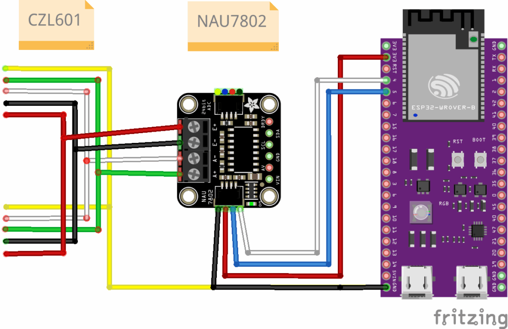
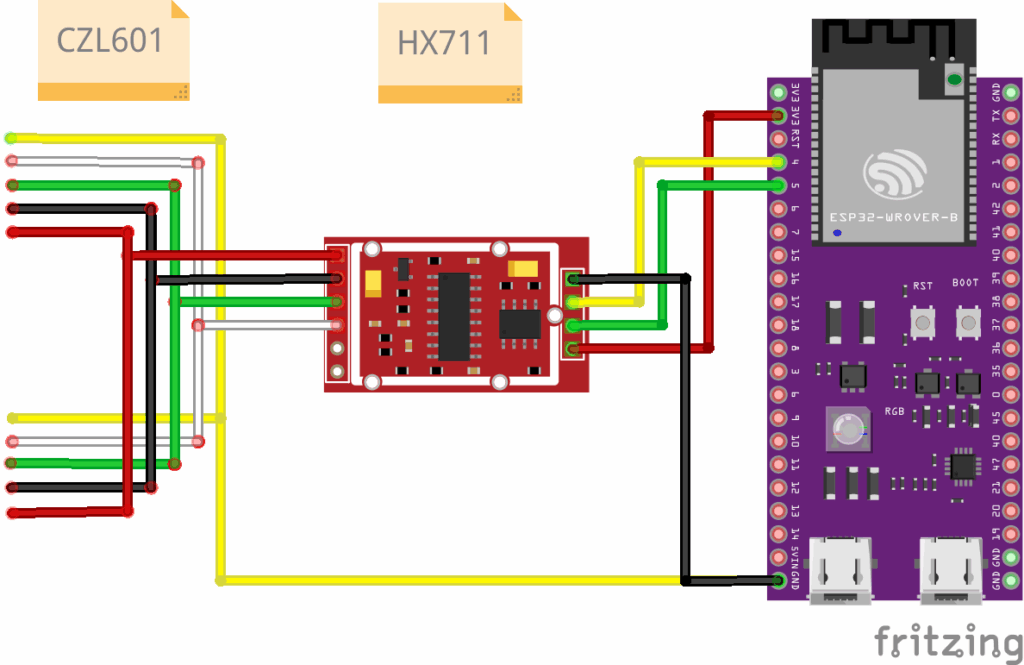
I connected it like this:
The code for the test setup:
i2c:
  sda: GPIO4
  scl: GPIO5
  frequency: 400khz
  scan: true

sensor:
  - platform: nau7802
    name: "NAU7802 Weight"
    gain: 128
    ldo_voltage: "3.0V"
    update_interval: ${update_interval}
    filters:
     - calibrate_linear:
          datapoints:
          # measuring at 25 °C
           -  64429 -> 0
           -  166362 -> 4.58    # super with empty frames + tension belt
           -  392628 -> 14.58   # super with empty frames + tension belt + 10kg
           ...
button:
  - platform: template
    name: "Toggle Internal Calibration"
    on_press:
      - logger.log: "Internal calibration toggled"
      - nau7802.calibrate_internal_offset
This code exposes the internal calibration via a button. The documentation says the internal calibration should be called on temperature or parameter changes, this is an open TODO as well as compensating the temperature drift.
Additional new TODOs:
Support for the internal temperature sensor for the NAU7802-eshome-component
Support for channel B for the NAU7802-esphome-component
A proper state machine for the NAU7802-esphome-component (similar to the suggestion to the HX711-component in this pull-request)
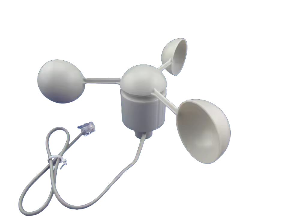
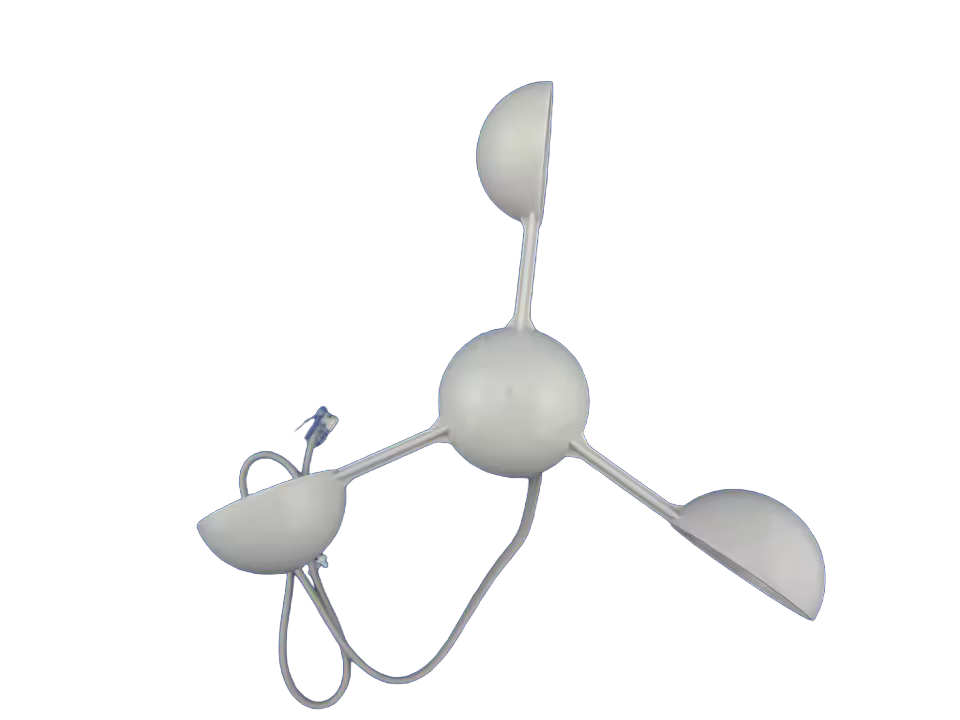
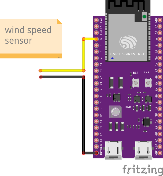
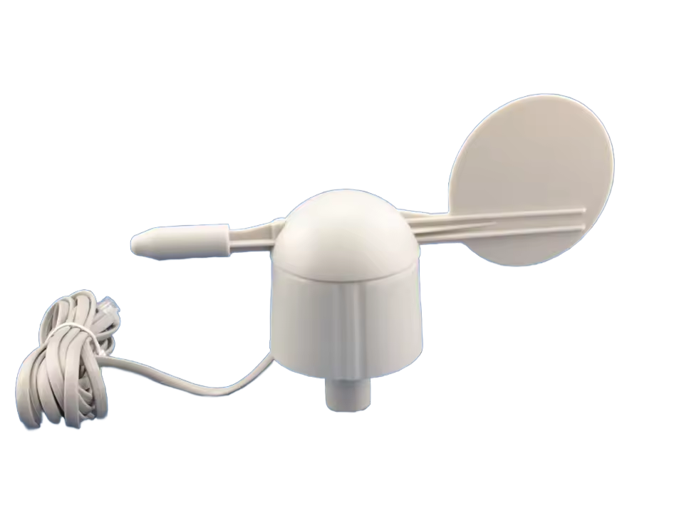
I bought a wind speed sensor from china, it’s a spare part for the “misol” weather stations, just search for “wind speed misol sensor aliexpress” for the product, it was less than 15€.
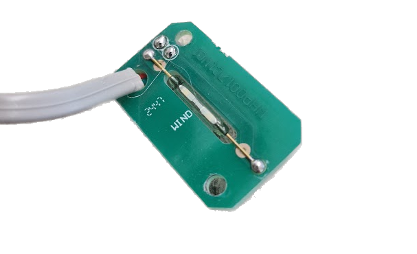
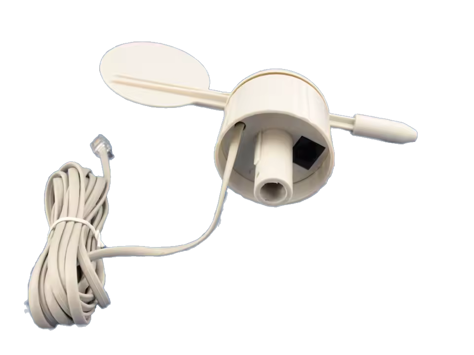
I unscrewed it to see how it works, technically it’s just a hall sensor.
For my test-setup, I simply cut off the connector (Don’t do this if you want to use it in combination with the wind direction sensor, it’s intended to be plugged in there!) and connected the wires directly to GND and GPIO4 and used the internal pull-up resistor:
The value “0.04” is 2.4kmh/60s (to convert it from esphome’s pulses/min to km/h). The value 2.4km/h is explained here in the datasheets I found in this wiki that seem to match my hardware: datasheet_1 datasheet_2
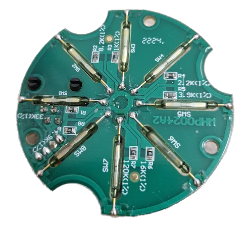
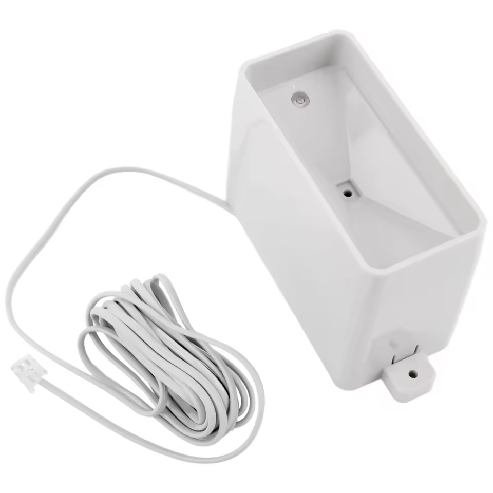
I bought a wind direction sensor from china, it’s a spare part for the “misol” weather stations, just search for “wind direction sensor misol aliexpress” for the product, it was less than 15€.
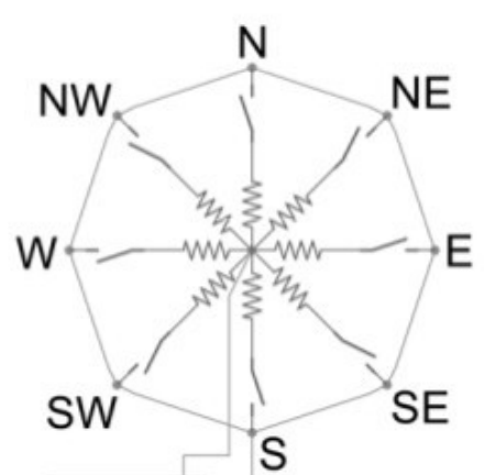
So it’s a few hall sensors that switch resistors connected in parallel. The magnet switches one or two of them at once:
The resistor values are given in the datasheet:
Direction (degrees)
Resistance (ohms)
0
33K
22.5
6.57K
45
8.2K
67.5
891
90
1K
112.5
688
135
2.2K
157.5
1.41K
180
3.9K
202.5
3.14K
225
16K
247.5
14.12K
270
120K
292.5
42.12K
315
64.9K
337.5
21.88K
Every second entry in this table is a combination of the entries below and above when both switches are triggered and is defined by the formular for two resistors connected in parallel:
$$R = \frac{R_1 \cdot R_2}{R_1 + R_2}$$
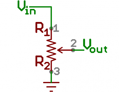
So we have to measure the resistance of the sensor via the ADC. Therefore a voltage divider is needed. A voltage divider looks like this:
R2 is the variable resistor that is the sensor. R1 has to be chosen correctly so that it matches the range of R2, the value of Vin and the desired measuring range on Vout.
According to the datasheets we have to measure resistances for R2 that can be between 688 Ω and 120 kΩ. The ADC of the ESP32S3 accepts up to 3100 mV with ADC_ATTEN_DB_11 (that’s Vout), Vin is 3.3V from the ESP32.
Now the value for R1 has to be calculated for the biggest possible resistor, so we have R2=120 kΩ, Vin=3.3V and Vout≤3.1V:
That’s a good value: with it we get 3.089V on Vout for 120kΩ which is about 99.6% of the maximal voltage of 3.1V the ADC of the ESP323 can handle. So we can get up to 3.089V of the reference voltage of 3.3V, that’s 93.6% of the theoretical range. The ADC has 12 bits, that means we have a theoretical measuring range of 212=4096 values, 93.6% of it are ≈3834, so we have a resolution of round about 120kΩ/3834 ≈ 31.3Ω. That’s sufficient, the minimal difference between the resistors we want to measure is more than 100Ω.
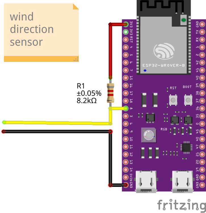
So we can wire the sensor up now via a properly chosen voltage divider:
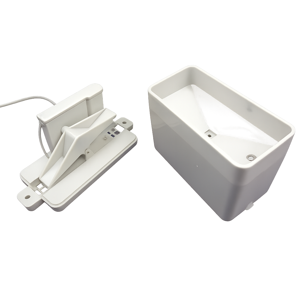
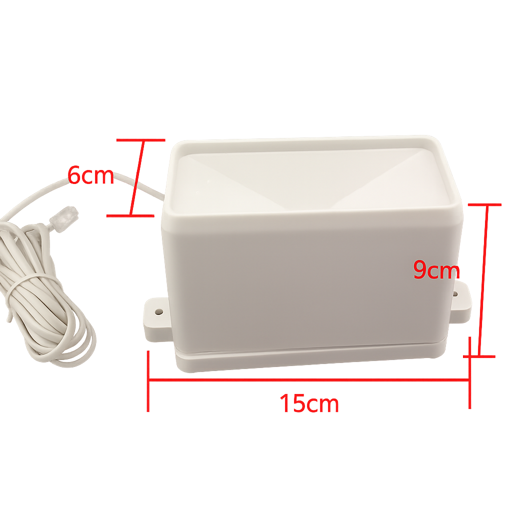
I bought a rain gauge from china, it’s a spare part for the “misol” weather stations, just search for “rain gauge sensor aliexpress” for the product, it was less than 15€. Technically it’s just a hall sensor.
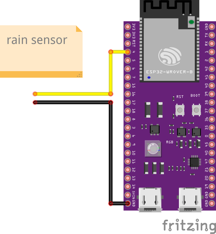
For my test-setup, I simply cut off the connector and connected the wires directly to GND and GPIO4 and used the internal pull-up resistor:
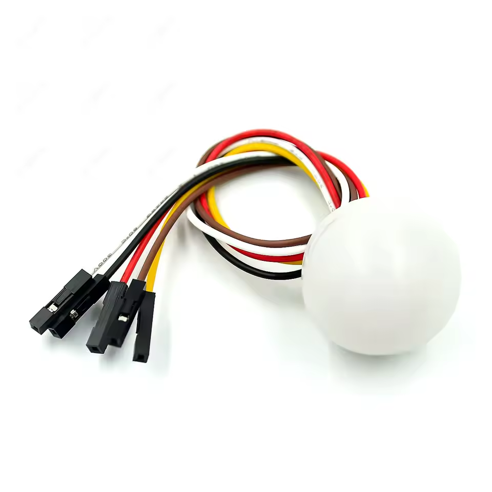
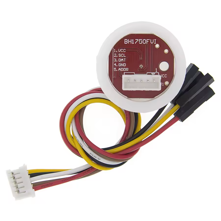
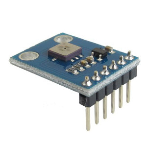
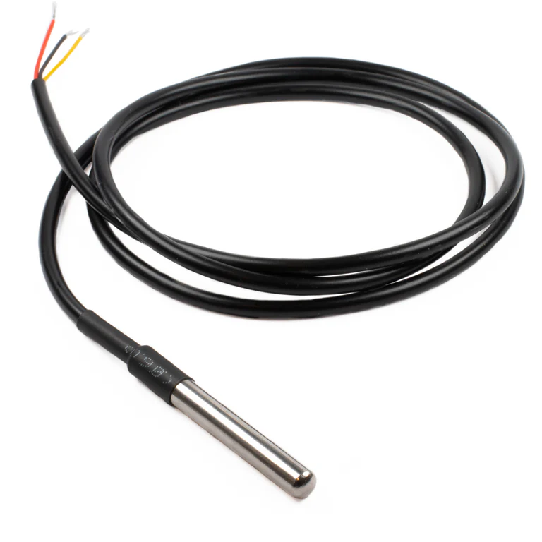
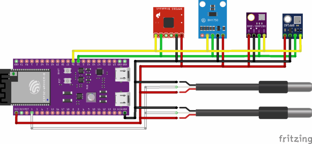
I’m still unsure which sensors to use in production, so I started experimenting:
I connected a bmp085, a waterproof bh1750, a Si7021 and a bme280 via I2C. Two DS18B20s that will be built in in the lid of the hive and into its center are connected via 1-wire.
But: Since my house is automated with homeassistant, esphome, a lot of ESP32s and my bee-hives are in WIFI-range, I decided to rebuild the beelogger-functionality on esphome basis.
Additional arguments for realizing it with an ESP32 instead of an Arduino or STM32 might be:
more CPU power
more RAM & flash (up to 8 MB RAM & 16 MB flash)
integrated WIFI
probably less power consumption when using deep sleep modes
A DSP for audio analysis
more ADCs with higher resolution (depending on the ESP32 variant used)
a built-in RTC
the comfort of esphome:
OTA updates
a built-in automated connection to homeassistant
a webinterface on the device
no complex sketches to maintain, just a .yaml-config
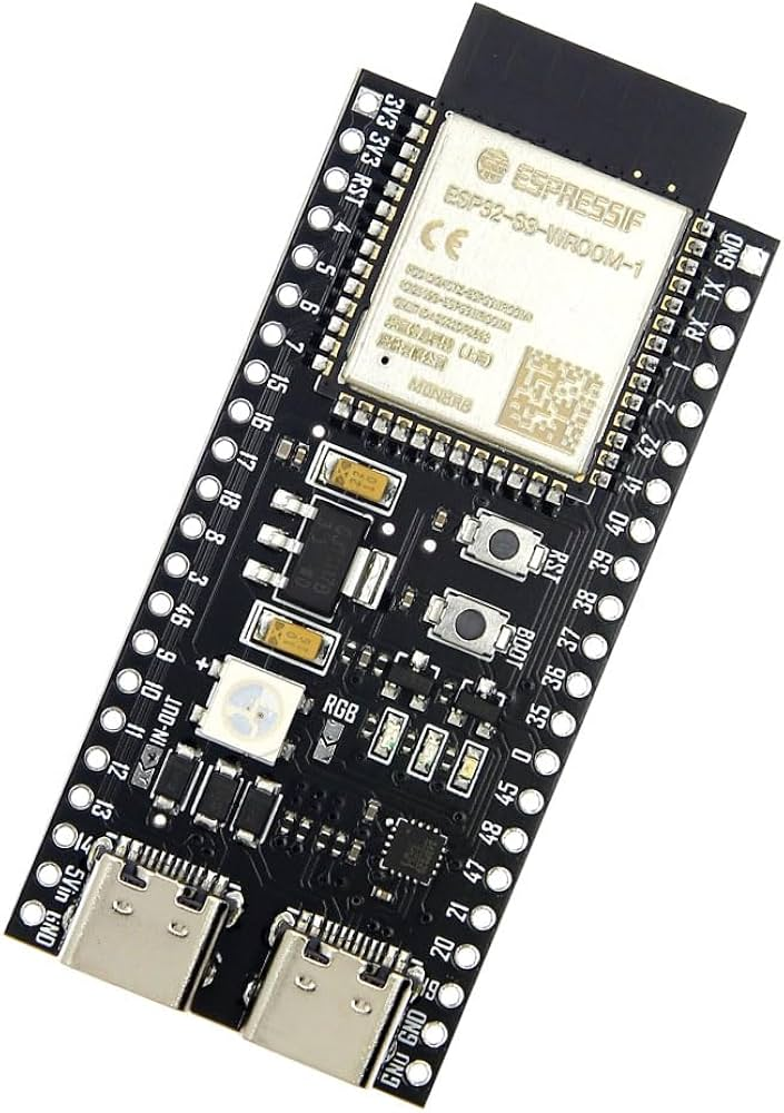
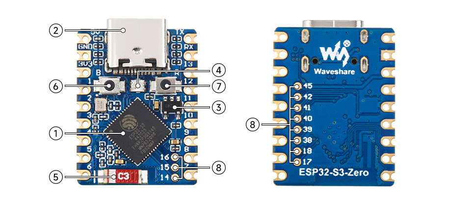
Desicion: I’m going to use an ESP32-S3-N16R8 and / or the ESP32-S3-Zero
The ESP32-S3-N16R8 provides:
a dual-core 32-bit microprocessor with 240 MHz
8MB of additional PSRAM and 16MB flash,
2.4 GHz Wi-Fi (IEEE 802.11b/g/n) and Bluetooth® 5 (LE)
An hardware RTC
Two general-purpose SPI ports
Three UARTs
Two I2Cs
Two I2Ss
Pulse counter
Two 12-bit SAR ADCs, up to 20 channels
Four 54-bit general-purpose timers
52-bit system timer
Three watchdog timers
DSP-hardware
Four power modes designed for typical scenarios: Active, Modem-sleep, Light-sleep, Deep-sleep
A lot of GPIOs 🙂
It’s the currently most powerful ESP32, its hardware should be more than enough for the task 😀 The Zero variant will be used when there are just a few PINs needed.
Realizing it will be a major project, but probably also a lot of fun 🙂
The TODOs I see so far, I’ll realize them in single test projects:
get all the desired sensors working properly
write an external component for esphome for the audio-analysis
write a component for esphome for the bee counter hardware
write a component for esphome to connect to the beelogger-server
care about the power management
logging to SD-card/flash
properly wiring it all up at the end, making it electronically fail safe, soldering it onto a prototype-board
install everything in proper cases with proper connectors and install it in a bee hive
realize additional ideas, they will for sure come up when working on this project 😉